Motion Hydraulics
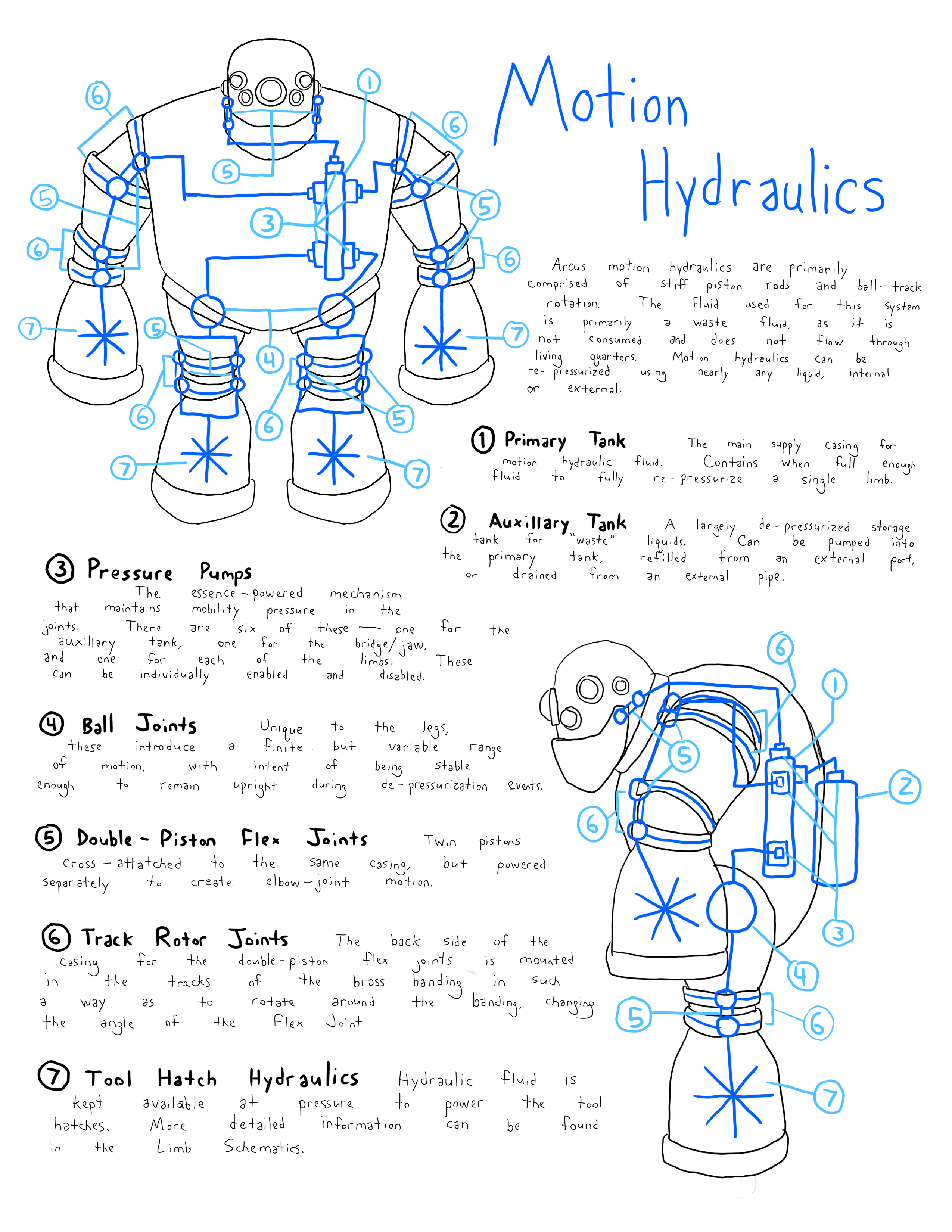
Arcus motion hydraulics are primarily comprised of stiff piston rods and ball-track rotation. The fluid used for this system is primarily a waste fluid, as it is not consumed and does not flow through living quarters. Motion hydraulics can be re-pressurized using nearly any liquid, internal or external.
1. Primary Tank
The main supply casing for motion hydraulic fluid. Contains, when full, enough fluid to fully re-pressurize a single limb.
2. Auxillary Tank
A largely de-pressurized storage tank for "waste" liquids. Can be pumped into the primary tank, refilled from an external port, or drained from an external pipe.
3. Pressure Pumps
The essence-powered mechanism that maintains mobility pressure in the joints. There are six of these - one for the auxillary tank, one for the bridge/jaw, and one for each of the limbs. These can be individually enabled and disabled.
4. Ball Joints
Unique to the legs, these introduce a finite but variable range of motion, with intent of being stable enough to remain upright during de-pressurization events.
5. Double-Piston Flex Joints
Twin pistons cross-attached to the same casing, but powered separately to create elbow-joint motion.
6. Track Rotor Joints
The back side of the casing for the double-piston flex joints is mounted in the tracks of the brass banding in such a way as to rotate around the banding, changing the angle of the flex joint.
7. Tool Hatch Hydraulics
Hydraulic fluid is kept available at pressure to power the tool hatches. More detailed information can be found in the Limb Schematics.
Note: Limb Schematics were not created during this project's lifetime.
Internal Communications
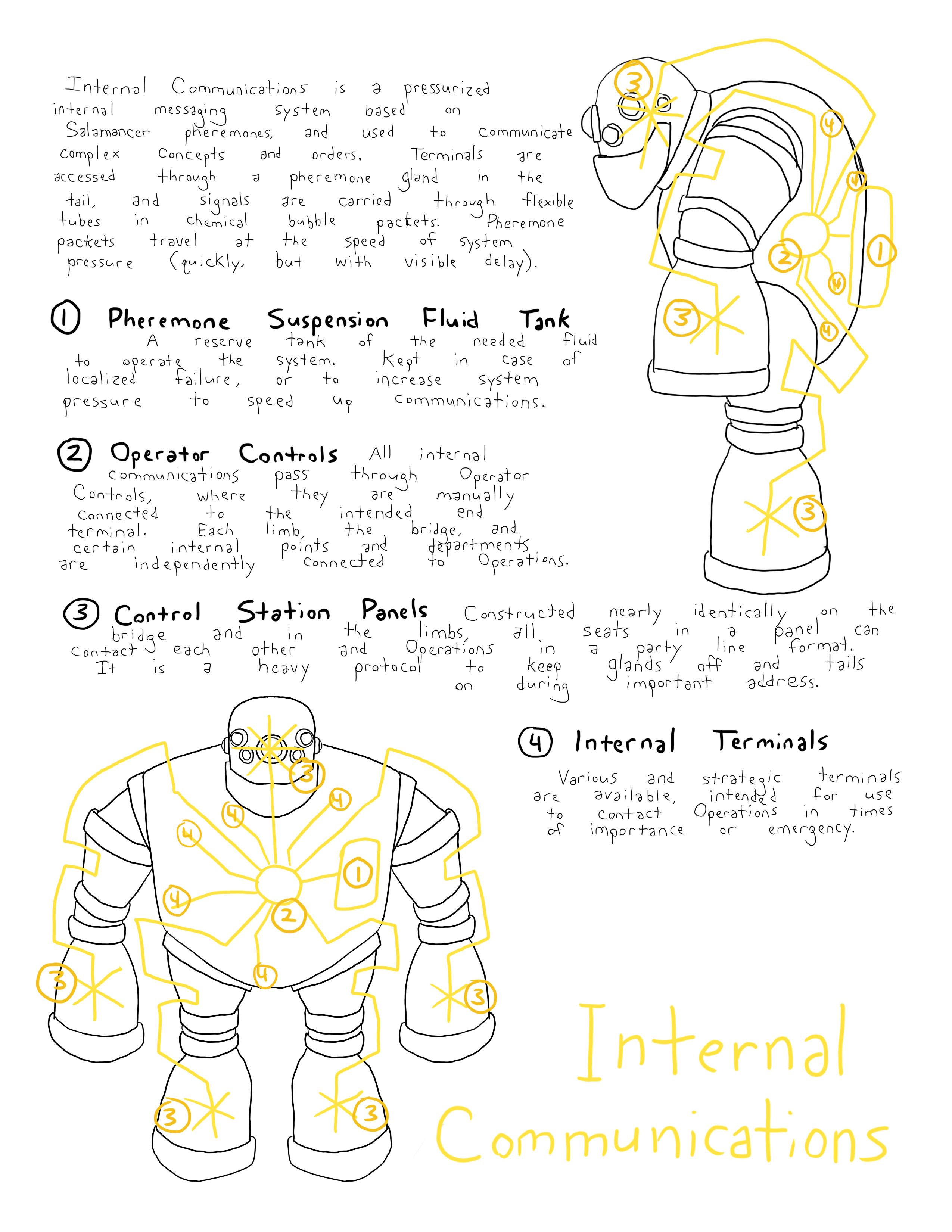
Internal Communications is a pressurized internal messaging system based on Salamancer pheremones, and used to communicate complex concepts and orders. Terminals are accessed through a pheremone gland in the tail, and signals are carried through flexible tubes in chemical bubble packets. Pheremone packets travel at the speed of system pressure (quickly, but with visible delay).
1. Pheremone Suspension Fluid Tank
A reserve tank of the needed fluid to operate the system. Kept in case of localized failure, or to increase system pressure to speed up communications.
2. Operator Controls
All internal communications pass through Operator Controls, where they are manually connected to the intended end terminal. Each limb, the bridge, and certain internal points and departments are independently connected to Operations.
Control Station Points
Constructed nearly identically in the bridge and in the limbs, all seats in a panel can contact each other and Operations in a party line format. It is a heavy protocol to keep glands off and tails on during important communications.
4. Internal Terminals
Various and strategic terminals are available, intended for use to contact Operations in times of importance or emergency.
DewDr0ptics (dDr0px)
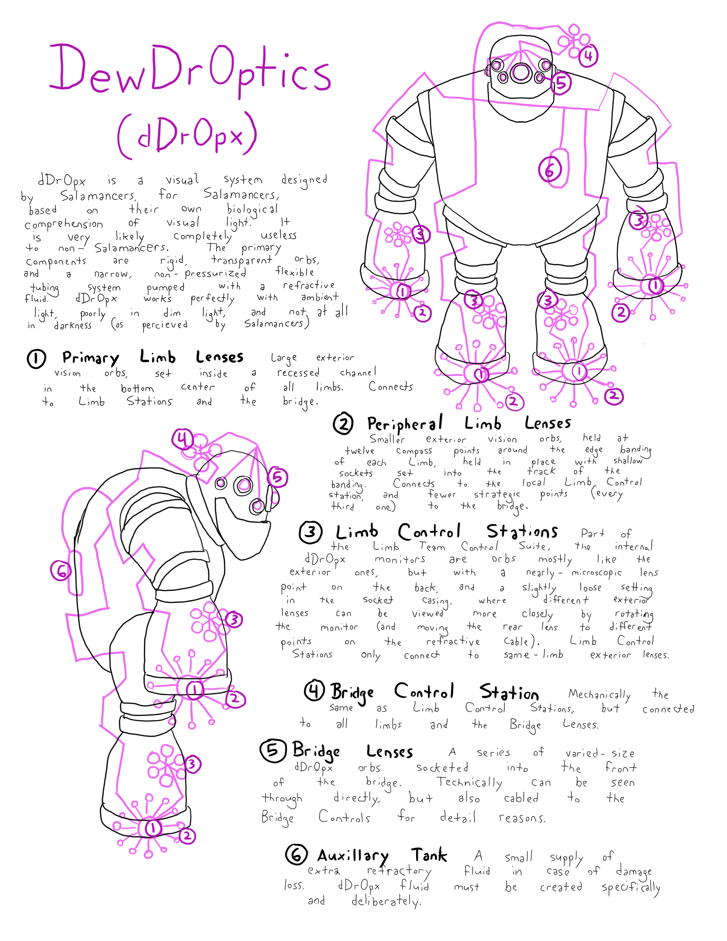
dDr0px is a visual system designed by Salamancers, for Salamancers, based on their own biological comprehension of visual light. It is very likely completely useless to non-Salamancers. The primary components are rigid, transparent orbs, and a narrow, non-pressurized tubing system pumped with a refractive fluid. dDr0px works perfectly with ambient light, poorly in dim light, and not at all in darkness (as percieved by Salamancers)
1. Primary Limb Lenses
Large exterior vision orbs, set inside a recessed channel at the bottom center of all limbs. Connects to Limb Station and the bridge.
2. Peripheral Limb Lenses
Smaller exterior vision orbs, held at twelve compass points around the edge banding of each Limb, held in place within shallow sockets set into the track of the banding. Connects to the local Limb Control Station, and fewer strategic points (every third one) to the Bridge.
3. Limb Control Station
Part of the Limb Team Control Suite, the internal dDr0px monitors are orbs mostly like the exterior ones, but with a nearly-microscopic lens point on the back, and a slightly loose setting in the socket casing, where different exterior lenses can be viewed more closely by rotating the monitor (and moving the rear lens to different points on the refractive cable). Limb Control Stations only connect to same-limb exterior lenses.
4. Bridge Control Station
Mechanically the same as Limb Control Stations, but connected to all limbs and the Bridge Lenses.
5. Bridge Lenses
A series of varied-size dDr0px orbs socketed into the front of the bridge. Technically can be seen through directly, but also cabled to the Bridge Controls for detail reasons.
6. Auxillary Tank
A small supply of extra refractory fluid in case of damage loss. dDr0px fluid must be created specifically and deliberately.
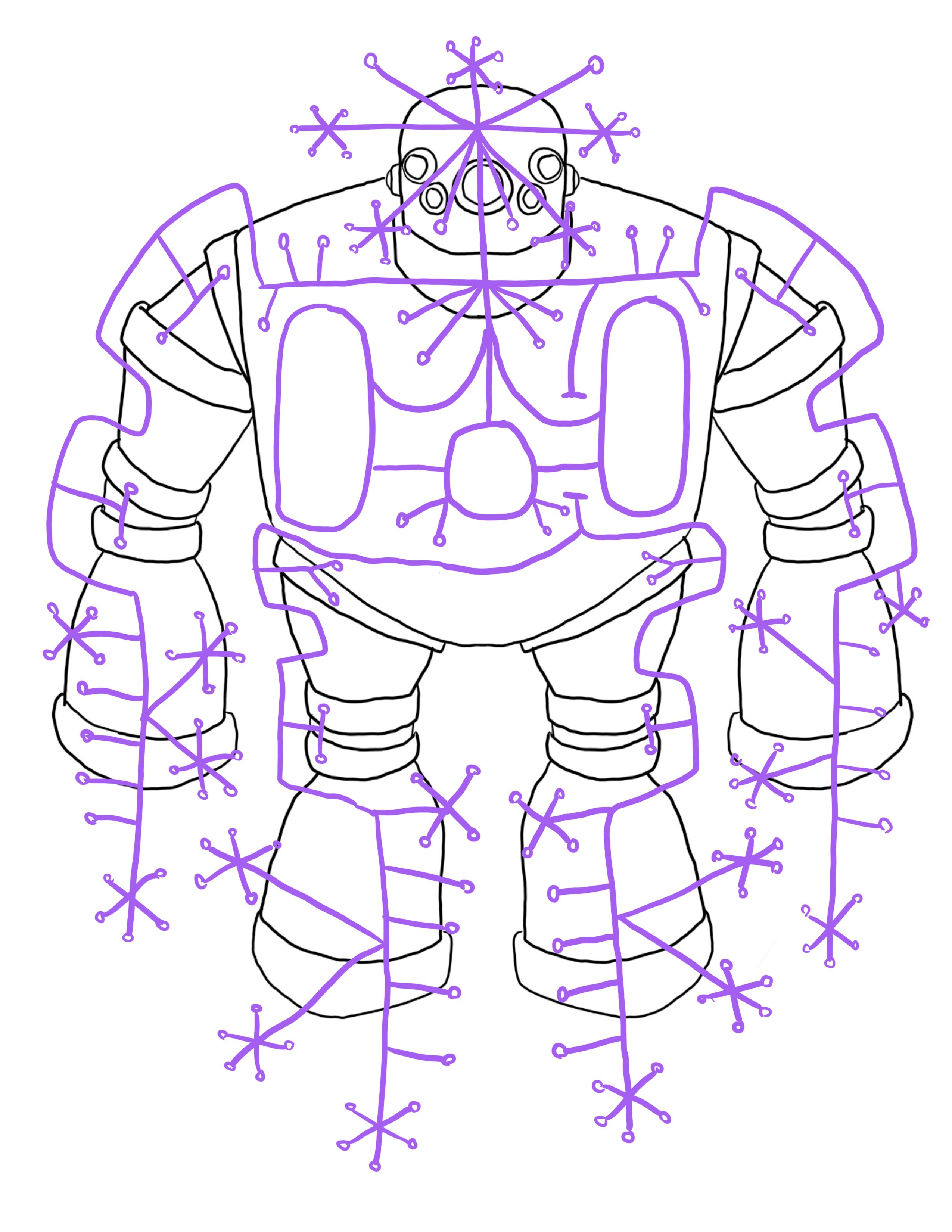
Note: This was the mapping for the Essence; the actual lifeblood power of the mech. Written details were not finished.